Products · Boilers & Heat Recovery

Waste Heat Recovery Exchangers

To establish the project design basis for “Waste Heat Recovery Exchangers”, confirm “Hot/cold streams and heat recovery” and its inputs: Specify both stream properties and flows, inlet/outlet conditions, duty and required approach, fouling and allowable pressure drops. Final values, supply limits and acceptance criteria are recorded in approved engineering documents; no generic capacity or catalogue guarantee is assumed.

Waste Heat Recovery Exchangers

From project definition to delivery

Engineering intent and design approach

Engineering of Waste Heat Recovery Exchangers concentrates on gas and steam temperature profiles, pinch and approach temperatures, steam conditions, circulation, gas-side pressure drop, water chemistry, metallurgy, fouling and start-up transients. The selected configuration is verified against normal, minimum, start-up, shutdown and credible upset cases, then checked for operability, maintainability, energy use, process safety and site interfaces before the design is frozen.

The design basis for Waste Heat Recovery Exchangers is defined from service data, design conditions, and battery limits. For this equipment, Hot/cold streams and heat recovery and Feed and thermal conditions must be completed in the datasheet and design documents; performance values and guarantees are set only after the project basis is approved.

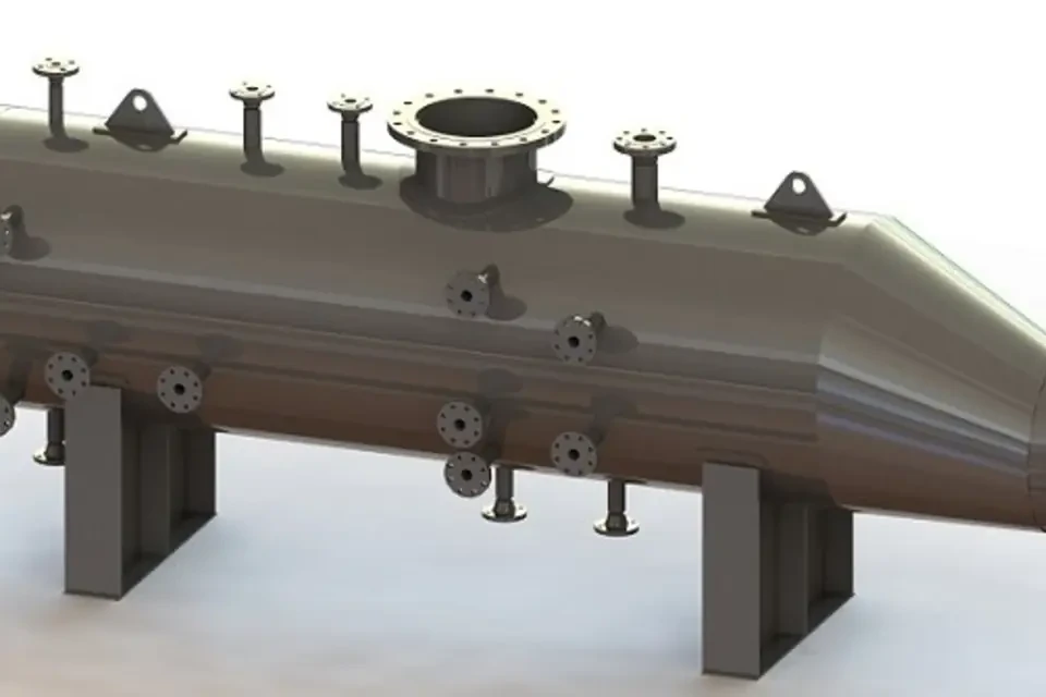
Mechanical design and materials

Materials, corrosion allowance, sour-service requirements, piping classes, nozzle design, insulation, coating, supports and maintenance access are coordinated with the actual process conditions and project code hierarchy.

Control, safeguarding and operation

Control philosophy, alarms and trips, cause-and-effect logic, interlocks, start-up and shutdown sequences, safe depressurization and operator access are developed consistently from the P&IDs through functional testing.

Layout, utilities and interfaces

Battery limits, tie-in points, structural loads, cabling, instrumentation, drains, vents, access routes, lifting envelopes and shipping constraints are controlled through coordinated models and interface drawings.

From project definition to delivery

Clear inputs and contract-ready outputs

Proposal quality depends on complete input data and an explicit acceptance basis. The following lists provide a practical starting point and are completed during technical clarification.

Recommended RFQ information

  • “Feed and thermal conditions”: Record feedwater/process-gas quality/flow, fuel, hot-gas conditions, inlet/outlet temperature and fouling/corrosion.
  • “Heat-transfer arrangement and side constraints”: Provide flow arrangement, fouling/corrosion, thermal expansion, cleaning access and pressure-drop limits for each side.
  • Site and ambient data, hazardous-area classification and HSE requirements
  • Available utilities with pressure, temperature and capacity
  • Applicable standards, materials, supply limits and owner document formats

Typical engineering and supply deliverables

  • Equipment datasheet and design basis for “Waste Heat Recovery Exchangers”, with service-relevant calculations where included in the supply scope.
  • PFDs, P&IDs, equipment list and technical datasheets
  • Control philosophy, cause and effect, I/O definition and utility summary
  • Plot plan, 3D model, foundation loads and fabrication drawings
  • Inspection and test plans, FAT records, final data book and commissioning support

Technical Datasheet

Technical Datasheet — Waste Heat Recovery Exchangers

The figure below is the published upper capacity for one gas-turbine-exhaust WHRU product family. It is not a universal exchanger range or a guaranteed duty for another exhaust composition or site.

Published equipment-family or project data only; not a universal standard limit or Delham rating/guarantee.
ParameterPublished valueReference basisApplicability / limit
Published WHRU capacity ceilingUp to 135 MWCapacity published for one waste-heat recovery unit family using gas-turbine exhaust.Product-family ceiling only; confirm whether the project duty is thermal/electrical, exhaust mass flow, temperature, composition and allowable backpressure.
Published heating-media optionsWater; water-glycol; thermal oil; regeneration gasMedia listed for the same WHRU family, depending on application.Select the medium and pressure boundary from the process duty, materials, freeze/thermal-degradation limits and applicable pressure-equipment code.
Published configuration optionsVertical or horizontal; integral/external bypassArrangement and bypass options listed for the same WHRU offering.Orientation, bypass sizing, bundle removal, gas-side pressure drop and thermal expansion require project-specific checks.

Published technical source

Delham Engineering

Define the scope around real project data

Send the available process data, battery limits and expected document list for a technical proposal. The engineering team will identify missing information through a structured clarification register.

Submit technical enquiry