معرفی
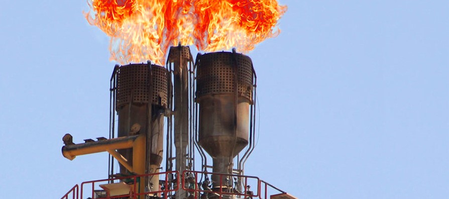
شعله ور آخرین خط دفاعی در سیستم آزادسازی اضطراری ایمن در یک پالایشگاه یا کارخانه شیمیایی است. از آن برای دفع محصولات تصفیه شده و هدر رفته از پالایشگاه ها، گازهای غیرقابل بازیافتی که با نفت از چاه های نفت بیرون می آیند، گازهای تخلیه شده از کوره های بلند، گازهای استفاده نشده از کوره های کک و آب گازی صنایع شیمیایی استفاده می شود.
فلر وسیله ای برای دفع ایمن جریان بخار از تاسیسات خود با سوزاندن آنها در شرایط کنترل شده به گونه ای که تجهیزات یا پرسنل مجاور در معرض خطر قرار نگیرند و در عین حال رعایت مقررات زیست محیطی کنترل آلودگی و الزامات روابط عمومی را فراهم می کند. . اینها می تواند باشد:
گازهایی که باید به طور مداوم به عنوان زباله حذف شوند.
گازهایی که گهگاه باید از تجهیزات برای اهداف تعمیر، نگهداری یا کاهش فشار تخلیه شوند.
خروج گازها از طریق نشت یا منفجر شدن سوپاپ های ایمنی.
گازهایی که باید حذف شوند زیرا خطرناک هستند، به عنوان مثال. خطرات آتش سوزی.
همه این گازها و مایعات تبخیر شده ممکن است به سادگی در هوا آزاد نشوند. آنها اتمسفر را آلوده می کنند و برای انسان ها، حیوانات و گیاهان خطرناک هستند (آتش، سم، و انفجار). سیستم شعله ور نقش حیاتی در یک کارخانه ایفا می کند. بسیار مهم است که باید ارتباط بسیار خوبی بین این کارخانه و سایر کارخانه های متصل به فلر وجود داشته باشد.
نوع شراره
شراره ها را می توان در دسته های عمده زیر دسته بندی کرد:
(الف.1) عمودی
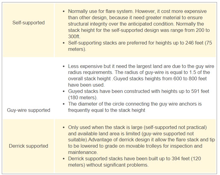
سه نوع پشتیبانی پشته ای در دسترس است، دارای پشتیبانی از خود، پشتیبانی از سیم سیم و پشتیبانی از دریک.

(الف-2) افقی
مایعات و گازهای شعله ور شده به یک مشعل افقی که به یک گودال یا حفاری تخلیه می شود هدایت می شوند.
(ب-1) شراره های بدون دود
شراره های بدون دود هر دود قابل توجه را در محدوده مشخصی از جریان ها از بین می برند.
احتراق بدون دود با استفاده از هوا، بخار، انرژی فشار یا وسایل دیگر برای ایجاد تلاطم و جذب هوا در جریان گاز شعلهور به دست میآید.
مقررات محلی و الزامات خاص گیاه عموماً سوزاندن بدون دود را تعریف می کنند. کدورت با مقیاس شماره گذاری رینگلمن تعریف می شود.
معمولاً تمایل به کشیدن سیگار تابعی از ارزش حرارتی گاز و ساختار پیوند هیدروکربنها است. سریهای پارافینی هیدروکربنها کمترین تمایل به تولید دود را دارند، در حالی که سریهای هیدروکربنهای الفین، دیالفینیک و آروماتیک تمایل بسیار بیشتری به تولید دارند. دود.
فلرهای بدون دود را می توان با یک سیستم کمک بخار یا کمک هوا برای بهبود احتراق ارائه کرد. یک سیستم کمکی هوا از فن ها برای تامین انرژی اختلاط در نوک استفاده می کند.
(B-2) شراره های بدون دود
شراره های بدون دود از هیچ روش بیرونی (هوا، بخار و غیره) استفاده نمی کنند.
فلرهای بدون دود معمولاً، اما نه به طور انحصاری، شعلههای یک نقطهای هستند. شرارههای بدون دود را میتوان برای تکمیل فلرهای بدون دود زمانی که ظرفیت مشعل بدون دود از آن فراتر رفت، استفاده کرد.
شرارههای بدون دود برای جریانهای هیدروکربنی یا بخاری استفاده میشوند که باعث سیگار کشیدن نمیشوند یا زمانی که دود نگران کننده نیست.

Flare Head (TIP)
نوک فلر آخرین وسیله سیستم فلر است. برای سوزاندن گاز بدون مایع استفاده می شود، به جز مقدار کمی که به دلیل انتقال از درام مربوطه است.
شعله ور شدن لوله
یک نمودار ساده از نوک شعله ور لوله معمولی در شکل 6 نشان داده شده است. 0.3 ماخ برای جریان پیوسته.
تعمیر و نگهداری فلر لوله معمولی بسیار کم است.
هر نوک شعله باید اشتعال قابل اعتمادی داشته باشد و در بدترین شرایط آب و هوایی پایداری شعله ایجاد کند.
تثبیت شعله با استفاده از حلقه نگهدارنده شعله طراحی شده ویژه که در نوک شعله تعبیه شده است به دست می آید. این دستگاه با ایجاد گرداب هایی در پایین دست تثبیت کننده، جلوی شعله را تثبیت می کند تا جریان اصلی گاز را مشتعل کند و از بلند شدن شعله جلوگیری کند.
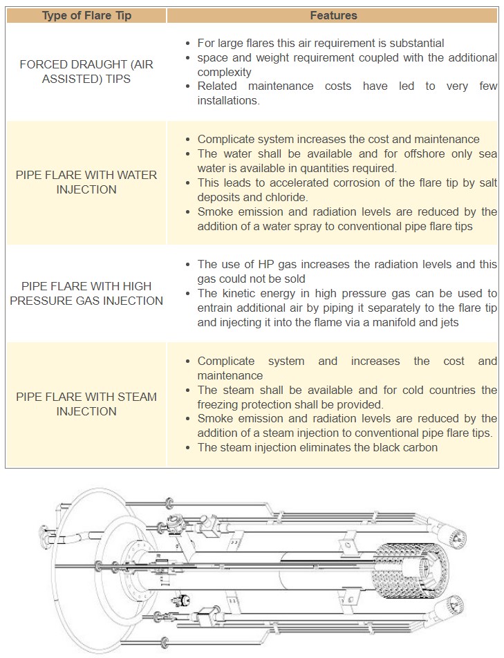
انواع مختلفی از فلر ساده لوله تک نوک وجود دارد و برخی از آنها در زیر مورد بحث قرار گرفته اند و به طور کلی برای تولید توصیه نمی شوند، مگر در موارد خاص، عمدتا برای حل مشکلات دود:
نکات درافت اجباری (با کمک هوا).
PIPE FLARE با تزریق آب
شعله ور لوله با تزریق گاز فشار بالا
فلار لوله با تزریق بخار
جدول 1- فشرده سازی انواع مختلف نوک فلر

مشعل های خلبان
تعداد مشعل های پیلوت توزیع شده در اطراف نوک شعله تابع قطر نوک و انحراف شعله پیلوت پیش بینی شده در اثر باد است. ارقام معمولی در زیر آورده شده است، اگرچه طراحی واقعی باید توسط فروشنده فلر انجام شود.
مصرف گاز در هر مشعل پیلوت معمولاً 8-10 نیوتن متر مکعب در ساعت است
هر خلبان توسط یک خط گاز جداگانه تغذیه می شود که از سیستم جرقه زنی کور شده است. مشعل های پایلوت برای اطمینان از منبع جرقه زنی مداوم در پشته شعله ور ارائه می شوند. این سیستم شامل چندین مشعل پیلوت پیوسته است که در اطراف نوک فلر چیده شدهاند و با سیستم احتراق خلبان کنترلشده از راه دور تکمیل میشود تا از خرابی شعله اطمینان حاصل شود. نکته اصلی سیستم پایلوت قابلیت اطمینان است. طراحی آن باید دارای ویژگی هایی باشد که به آن اجازه می دهد تحت شرایط آب و هوایی نامطلوب، به ویژه سرعت باد بالا عمل کند.

سیستم احتراق
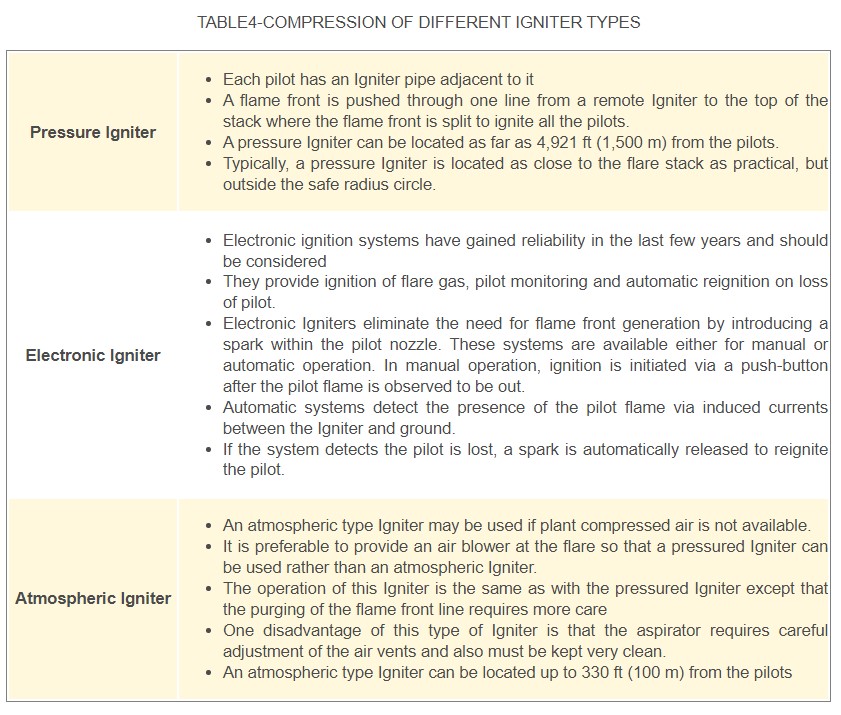
یک سیستم جرقه زنی پایلوت برای امکان اشتعال مشعل های پیلوت پیوسته در هنگام راه اندازی یا از کار افتادن سهوی شعله مشعل ها ارائه شده است. جرقه زن ها عموماً از نوع انتشار شعله هستند که در آن یک مخلوط قابل اشتعال از پیش مخلوط شده از هوا و گاز سوخت جرقه الکتریکی می زند و جلوی شعله حاصل از طریق یک لوله باز کوچک به هر مشعل راهنما منتشر می شود، طول این لوله باید حدوداً محدود شود. 100-150 متر، با لوله طولانی تر، سیستم به درستی کار نمی کند. برخی دیگر از مفاهیم در دست توسعه هستند و به نظر می رسد جرقه های جرقه ای با انرژی بالا سابقه خوبی دارند.
احتراق معمولاً به صورت دستی از طریق یک دکمه فشاری محلی انجام می شود، اگرچه سیستم های جرقه زنی خودکار که با دریافت سیگنال هشدار خرابی شعله فعال می شوند در دسترس هستند. با این حال، سیستم های دستی توصیه می شود.

سیستم کنترل
سیستم کنترل شعله می تواند کاملاً خودکار یا کاملاً دستی باشد. اجزای یک سیستم شعله ور که می تواند به طور خودکار کنترل شود شامل گاز کمکی، تزریق بخار و سیستم جرقه زنی است.
مصرف گاز سوخت را می توان با اندازه گیری مداوم نرخ جریان گاز دریچه و محتوای گرما و تنظیم خودکار مقدار سوخت کمکی برای حفظ حداقل مورد نیاز به حداقل رساند.
مصرف بخار را نیز می توان با کنترل جریان بر اساس نرخ جریان گاز دریچه به حداقل رساند.
همچنین می توان جریان بخار را با استفاده از مانیتورهای دود بصری کنترل کرد. پانل های جرقه زنی خودکار وجود شعله را با حسگرهای بصری یا حرارتی حس می کنند و در صورت بروز شعله، خلبان ها را دوباره مشتعل می کنند.
تجهیزات جانبی
ساختار پشتیبانی
لوله کشی
نردبان و سکو
سیستم کنترل
مهر و موم مایع (اختیاری)
مهر و موم سرعت (اختیاری)
مهر و موم مولکولی (اختیاری)
ناک اوت درام (اختیاری)
چراغ هشدار هواپیما و نقاشی (اختیاری)
مشعل های خلبانی
طراحی / محاسبات
با استفاده از نرم افزارهای مهندسی کامپیوتری مانند فلارسیم و فست، طرح های دقیق و سفارشی سازی شده همراه با سناریوهای مختلف تولید می شود که با شبیه سازی می توان سیستم فلر عالی را تولید کرد.
تولید
شرکت مهندسی دلهام به عنوان سازنده جامع سیستم فلر، قطعات اصلی را تولید می کند و این قطعات را مطابق با مشخصات دقیق طراحی مونتاژ می کند.
فرآیند دقیق و دانش کاربردی ما به ما این امکان را داده است که چندین راه حل مهندسی ثبت شده و همچنین سیستم طراحی سفارشی را در صورت لزوم توسعه دهیم. در تمام مناطق تولیدی، رویه های بازرسی در حین فرآیند برای اطمینان از حفظ کیفیت محصول دنبال می شود.
در طول فعالیت های بازرسی در حین فرآیند، محصولات معیوب آشکار بررسی می شود. در صورت شناسایی نقص، همه رشتهها/ پرسنل مرتبط، یافتهها را بررسی کرده و اقدامات اصلاحی/پیشگیرانه لازم را تعیین خواهند کرد.
بازرسی / تست
نماینده کنترل کیفیت شرکت مهندسی دلهام و آژانس شخص ثالث (در صورت استفاده) برنامه دریافت، در حین فرآیند و بازرسی نهایی را برای تأیید و مستندسازی انطباق با الزامات مستند اجرا می کنند. نماینده کنترل کیفیت به مدیر پروژه گزارش می دهد و فعالیت های خود را با مهندس پروژه هماهنگ می کند که به همراه ناظر عمومی مسئولیت اجرای فعالیت های ساخت و ساز اختصاص داده شده از جمله کلیه الزامات کنترل کیفیت را بر عهده دارند.
بازرسی کنترل کیفیت دلهام، شاهد و نقاط نگهداری برای فعالیت های تامین کننده/پیمانکار فرعی در صورت نیاز با روش های کنترل کیفیت تدارکات که بازرسی کنترل کیفیت اجباری، شاهد و نقاط نگهداری را در صورت لزوم فراهم می کند، اجرا می شود. برای مشتریان امتیاز شاهد و نگهدار مطابق با الزامات قرارداد اجرا خواهد شد.
شرکت مهندسی دلهام بازرسی در حین فرآیند فعالیت های انقباض را مطابق با رویه های خاص کار و کنترل کیفی که مطابق با رویه های کنترل دستورالعمل ها، نقشه ها و رویه ها تهیه شده است، کنترل می کند.
شرکت مهندسی دلهام آزمایشهای اثبات مورد نیاز ساختار، سیستمها و اجزا را مطابق با روشهای کنترل کیفیت خاص و دستورالعملهای کاری انجام میدهد که شامل الزامات و محدودیت پذیرش مندرج در اسناد طراحی خاص است. رویه ها تهیه، بازنگری، تایید و کنترل دستورالعمل ها، ترسیم رویه ها برای اطمینان از برآورده شدن الزامات تست ها می باشد. تایید شده توسط پرسنل مجاز؛ کامل تحت شرایط کنترل شده؛ و مدارک مورد نیاز را تهیه کنید.
رویههای کنترل کیفیت که مخصوصاً برای آزمایش اثبات تهیه شدهاند شامل الزامات ابزار دقیق، محدودیتهای پذیرش، اسناد و مدارک و پذیرش نتایج است. رویههای کنترل کیفیت برای ارائه بازرسی مستقل کنترل کیفیت، از جمله تأیید و مستندسازی نتایج یا دادههای آزمایش اثبات، آماده میشوند.
تعمیر و نگهداری / بازسازی
ارائه تعمیر و نگهداری پیشگیرانه، تعمیر و نگهداری اصلاحی و همچنین تعمیر / بازسازی جامع در شرایط جدید. خدمات ما
تخصص شامل تجزیه و تحلیل و عیب یابی، مطالعات امکان سنجی، گزارش بازرسی، برچیدن/نصب، حمل و نقل، تست بازرسی، تعمیر عمده/جزئی و غیره است.
قطعات یدکی
حمل موجودی فراوان برای تامین مجموعه وسیعی از اجزای مربوط به شعله ور مانند تریپ فلر، سیستم جرقه زنی، سوپاپ ها، کابل ها و بسیاری موارد دیگر با در دسترس بودن تضمینی.
نصب و راه اندازی
با قابلیتهای قوی مدیریت پروژه، از جمله راهاندازی، ما به اجرای روان و به موقع پروژه اطمینان داریم. قابلیت های نصب شامل Guyed-Wired Supported-Derrick، supported-Self supported و غیره است.
قطعات یدکی
حمل موجودی فراوان برای تامین مجموعه وسیعی از اجزای مربوط به شعله ور مانند تریپ فلر، سیستم جرقه زنی، سوپاپ ها، کابل ها و بسیاری موارد دیگر با در دسترس بودن تضمینی.
Introduction
The flare is a last line of defense in the safe emergency release system in a refinery or chemical plant. It uses to dispose of purged and wasted products from refineries, unrecoverable gases emerging with oil from oil wells, vented gases from blast furnaces, unused gases from coke ovens, and gaseous water from chemical industries.
The flare provides a means of safe disposal of the vapor streams from its facilities, by burning them under controlled conditions such that adjacent equipment or personnel are not exposed to hazards, and at the same time obeying the environmental regulation of pollution control and public relations requirements. These could be Gases, which must be continuously removed as waste
Gases which occasionally have to be discharged from equipment for repair, maintenance or depressurization purposes
Gases escaping through leaks or safety valves blowing off
Gases, which have to be removed because they are dangerous, e.g. fire hazards
All these gases and evaporated liquids may not simply be released into the air. They would pollute the atmosphere and be dangerous for men, animals and plants (fire, poisen, and explosion).they are therefore all brought to one point high in the air and burnt there. the flare system plays a vital role in a factory. It is very important that there should be very good communication between this factory and all others connected to the flare.
Flare Type
Flares can be grouped under the following major categories
(A.1)VERTICAL
Three type of stack support available,there is self-supported,guy-wire supported and derrick supported

(A-2) HORIZONTAL
The flared liquids and gases are piped to a horizontal flare burner that discharges into a pit or excavation.
(B-1) SMOKLESS FLARES
Smokless flares eliminate any noticeable smoke over a specified range of flows
Smokless combustion is achieved by utilizing air,steam,pressure energy,or other means to create turbulence and entrain air with in the flared gas stream.
Local regulation and plant specific requirements generally define smokeless burning .Opacity is defined by ringelmann numbering scale
Typically the smoking tendency is function of the gas calorific value and of the bonding structure of the hydrocarbons.The paraffinic series of hydrocarbons have the lowest tendency to produce smoke ,whereas olefins,diolefinic,and aromatic series of hydrocarbons have a much higher tendency to produce smoke
Smokeless flares can be provide with a steam-assist or air-assist system to improve combustion.An air-assist system utilizes fans to provide mixing energy at the tip.

(B-2) NON-SMOKLESS FLARES
None-smokeless flares utilize no outside methods(air,Steam,ect.)
None-smokeless flares are typically,but not exclusively,single-point flares.None-smokless flares can be used to supplesment smokless flares when the capacity on the smokless flare is exceeded.
None-smokless flares are used for hydrocarbon or vapor streams that do not cause smoking or when smoke is not a concern.

Flare Head (TIP)
The flare tip is the last device of the flare system. It is used to burn the gas without liquid, except the small quantity due to the carryover from the associated drum.
PIPE FLARE
A simplified diagram of a conventional pipe flare tip is shown in Fig.6 pipe flare tip is always installed vertically and the gas velocity through it is limited at a maximum of 0.5 to 0.6 Mach for the emergency flow rate (non-continuous flow) and 0.3Mach for the continuous flow.
The maintenance of a conventional pipe flare is very low.
Any flare tip must offer reliable ignition and give flame stability under the most adverse weather conditions.
Flame stabilization is achieved by the use of specially designed flame retention ring built into the flare tip. This device stabilizes the flame front by creating vortexes downstream of the stabilizer to ignite the main gas stream and so help prevent flame lift-off.
There are many variations of the simple single tip pipe flare and some of these are discussed below and generally not recommended for production except in special cases mainly to solve the smoke problems.
FORCED DRAUGHT (AIR ASSISTED) TIPS
PIPE FLARE WITH WATER INJECTION
PIPE FLARE WITH HIGH PRESSURE GAS INJECTION
PIPE FLARE WITH STEAM INJECTION

PILOT BURNERS
The number of pilot burners distributed around the flare tip is function of the tip diameter and the predicted pilot flame deflection due to wind. Typical Figures are given below, although the actual design should be made by the flare vendor.
Gas consumption per pilot burner is typically 8-10 Nm3/h
Each pilot is fed by an individual gas line, which is blinded from the ignition system. Pilot burners are provided to ensure a continuous ignition source at the flare stack. The system consists of multiple continuous pilot burners arranged around the flare tip, supplemented by remote controlled pilot ignition system to ensure against flare failure. The prime consideration of the pilot system is reliability. Its design must incorporate features, which allow it to function under adverse weather conditions, particularly high wind speeds.
IGNITION SYSTEM
A pilot ignition system is provided to allow ignition of continuous pilot burners during start-up or inadvertent flame failure of burners. Igniters are generally of the flame propagation type in which a premixed flammable mixture of air and fuel gas is electrically sparked and the resulting flame front is propagated to each pilot burner through a small open ended pipe, the length of this pipe shall be limited at about 100-150m, with a longer pipe, the system does not work correctly. Some other concepts are under development and the high energy sparks igniters seem to have a good record
Ignition is normally performed manually through a local push button, although automatic ignition systems actuated on receipt of a flame failure alarm signal are available. However, manual systems are recommended.

Control System
Flare control system can be completely automated or completely manual. Components of a flare system which can be controlled automatically include the auxiliary gas, steam injection, and the ignition system.
Fuel gas consumption can be minimized by continuously measuring the vent gas flow rate and heat content and automatically adjusting the amount of auxiliary fuel to maintain the required minimum.
Steam consumption can likewise be minimized by controlling flow based on vent gas flow rate.
Steam flow can also be controlled using visual smoke monitors. Automatic ignition panels sense the presence of aflame with either visual or thermal sensors and reignite the pilots when flameouts occur.
Accessories
Support structure
Piping
Ladder and platform
Control system
Liquid seal (optional)
Velocity seal (optional)
Molecular seal (optional)
Knock out drum (optional)
Air craft warning light, and painting (optional)
Pilot burners
Design / Computing
Manufacturing
Our detailed process and application knowledge has allowed us to develop several patented engineering solutions as well as custom design system when required. In all manufacturing areas in-process inspection procedures are followed to ensure that product quality is maintained
During in-process inspection activities, check is made for obvious defective products. Where defects are identified all associated disciplines/personnel will review the findings and determine the necessary corrective/preventive actions.
Inspection / Test
Delham quality control inspection, witness, and hold points for supplier/subcontractor activities are implemented as needed, by procurement quality control procedures which provide for mandatory quality control inspection, witness, and hold points when necessary. For clients, witness and hold points will be implemented in accordance with contract requirements.
Delham Engineering company controls and dicuments in-process inspection of constriction activities in accordance with the specific work and quality control procedures, which are prepared in accordance with procedures for control of instructions, Drawings and Procedures
Delham Engineering company performs and/or oversees required proof tests of structure, systems and components in accordance with specific quality control procedure and work instructions, which incorporate the requirements , and acceptance limit contained in specific design documents. procedures are prepared, reviewed, approved, and control of instructions, drawing procedures to assures tests meet requirements; approved by authorized personnel; a complete under controlled conditions; and, provide for the required documentation
Quality control procedures prepared specially for proof testing include instrumentation requirements, acceptance limits, documentation, and acceptance of results. Quality control procedures are prepared, necessary, to provide independent quality control inspection, including verification and documentation of proof testing results or data.
MAINTENANCE / RECONDITION
Expertise include analysis& roubleshooting, feasibility studies, inspection report, dismantle/install, transport, inspect testing, major/minor repair, ect.

